Switching Power Supply Test---Step I
One: The Working Principle Of Switchable Power Supply
1, switching power supply is a high-frequency switching type energy conversion electronic circuit, often used as the power supply of equipment, common transformation classification: AC-DC, DC-DC, DC-AC, etc.
2. Schematic diagram of switching power supply

(1) After the mains enters the power supply, it first passes through the most advanced EMI filtering circuit. The main function of EMI filtering is to filter out the interference of the high-frequency pulse of the external power grid to the power supply, and reduce the electromagnetic interference of the switching power supply itself to the outside world. In fact, it is the characteristics of the inductor and capacitor, so that the AC frequency of about 50Hz can smoothly pass through the filter, and the high-frequency interference clutter above 50Hz will be filtered out by the filter.
(2) After EMI filtering, the relatively flat sine-wave alternating current obtained is sent to the pre-stage rectifier circuit for rectification, and the rectification work is performed by the full-bridge rectifier diode. After the full bridge rectifier diode rectification, the voltage all become positive phase voltage. However, the voltage obtained at this time still has large fluctuations, which must use a high-voltage filter capacitor for preliminary voltage regulation, and modify the waveform to a waveform with smaller fluctuations.
(3) The direct current is converted into high frequency pulsating direct current, this step is completed by the control circuit. The output part is fed back to the control circuit through a certain circuit, and the control circuit is used to adjust the switching time ratio of the high-frequency switching element to achieve the purpose of stabilizing the output voltage. At present, the control circuit has been integrated and made into various integrated circuits for switching power supply.
(4) The obtained pulsating DC is sent to the high-frequency switching transformer for voltage reduction. Then the low voltage filter circuit composed of diode and filter capacitor is rectified and filtered to obtain the pure static low voltage direct current used on the equipment.
3, switching power supply features:
(1) Switching power supply is a nonlinear power supply with light volume and weight.
(2) The power transistor works in the switching state, the power consumption on the transistor is small, and the conversion efficiency is high.
Two: Switchable Power Supply Testing Method
1, test project: loop gain, output impedance and output ripple and switching noise, etc
2. Loop gain test:

The switching power supply circuit can be regarded as a simple feedback control system
A negative feedback loop that generates self-excitation when GH=-1 (GH is called open-loop gain). Decomposition is: amplitude conditions: | GH | = 1, phase conditions: the phase of GH Φ = - 180 o
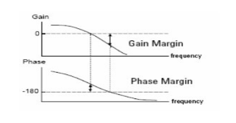
The open-loop characteristic is a very important parameter, which characterizes the stability of the feedback system. It is usually expressed in terms of gain margin and phase margin:
Gain margin: Φ=-180o, 0-Gain(dB)
Phase margin: when Gain=0, φ - (-180o)
It is usually represented by a Baud diagram

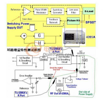
When testing the open-loop characteristics, the switching power supply should work in the closed-loop state to ensure the stability of the system state. The test scheme is as follows:
(1) Test equipment:
4395A, 41802A*2 (50ohm to 1Mohm adapter), 10441B*2 (probe), 9100-0855 (transformer)
(2) Test block diagram:

Switching power supply output plus electronic load; The input of the error amplifier is connected to the R port of the 4395A through a 41802A 1 MΩ input adapter and a 10441B probe. The switchable power supply output is connected to port A of 4395A through 41802A and 10441B; The RF output of the 4395A is added to the input of the error amplifier and the switching power supply output through a transformer. The R channel is used to measure the signal injected into the loop, and the A channel is used to measure the output signal of the loop. A/R is open loop characteristics of the loop. To ensure the accuracy of the measurement, a straight-through calibration is required before the test.
(3) Notes in the test:
A. In order to effectively inject RF energy into the component under test, the impedance of the transformer cannot be significantly lower than the impedance of the 4395A RF output port (50ohm); The transformer should not have resonant points in the test frequency range and should exhibit sensitivity to effectively inject signals. Transformer characteristics can be tested with impedance analyzer and 16047E test fixture:
B. The RF output signal of 4395A cannot be too large or too small. If the signal is too small, it will be noise, and if it is too large, the feedback loop will be saturated. The size of the signal depends on the transformer, and saturation depends on each switching power supply, so there is no fixed value.
You can change the excitation power at the time of measurement, look at A/R, A, R to determine a suitable excitation power.


